Much of the microscopy that we are doing nowadays is fluorescence microscopy. We will be explaining what that is in this page, in a simple way. Why do we use fluorescence in the microscope? As you probably seen so far, there are two important aspects in making a great picture in your microscope: One is resolution, i.e. you want high resolution, and the second thing is contrast, i.e. you want high contrast. Otherwise you would not see anything. What fluorescence offers is the high contrast image, as it is demonstrated in this image here:
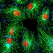 We have part of the cell, labeled in green. In green, we are looking at microtubules, i.e. labelled microtubules with the fluorescent dye.
We have part of the cell labeled in red, and that part is actually the nucleus or DNA. It is a red label attached to the histone protein. We also see that these labels stand out on a black background. Thus, we have a very high contrast image, i.e. we see what we want to look at whereas our background is totally absent. This gives an actually extremely high contrast image. What we already see in this specific image is that you get specificity. We can attach these fluorescent labels to specific proteins or molecules, specific dyes to specific places in the cell or wherever we want them. Thus, we can target them. They show what we want to see. Thus, fluorescence is quantitative. We can calibrate our system correctly. Areas where we have higher signal, those are areas where we have more of our protein that we are interested in. In this case, there is a lot more tubulin in the bright area.
Live Cell Imaging: Lastly and very importantly, fluorescence is compatible with imaging of living cells. The image shown above is a still image, but its actually part of a sequence of images that we took and when we now start playing those faster we see that it is actually a dividing cell. The microtubules assemble in the spindle. The spindle then pulls apart the chromosomes into daughter nuclei. So fluorescence is a great thing, a great thing for microscopy; but what is it really? What is kind of surprising still is that human kind has been aware of fluorescence for only about 150 years. One of the first descriptions of fluorescence was by Sir William Herschel. He was studying the aspect of an extract of the bark of the Chinchona tree.
 He held up this extract in the light of the sun that came through his window and he noted that the light of the sun induced a celestial blue light coming out of that extract of the bark of the Chinchona tree. We now try to repeat that 150 year-old experiment in the lab and we will be showing you that. The bark of the Chinchona tree is hard to come by, but luckily the active ingredient can be found in every super market in form of contained in tonic water. If we take the tonic water, pour it in a glass, we can start our experiment. The other part that we need is UV light to illuminate it. We can buy an urine tracker in a pet store. When we shine this UV light in the Quinine, in tonic water, you see that you get a blue light emitting from within the tonic water in its another wavelength, i.e. its a longer wavelength than this light with which we illuminate. That is why we see it a lot better. Our eyes are not very sensitive to this UV, but they are highly sensitive to the blue light in tonic water. Quinine is not the only compound that fluoresces, of course; otherwise it would be quite uninteresting. Already in the nineteenth century, scientists synthesized this dye called fluorescein that is highly fluorescent and when we shine blue light in that, we get yellow fluorescence coming out.
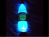
Another very well known dye is Rhodamine. When you shine green light in that, you get this orange-yellowish fluorescence coming out and so this is fluorescence. We use light of a lower wavelength (in this case of the quinine from the extract of the bark of the cinchona tree), we use UV light then the dye responds to that light by emitting light of higher wavelength (in this case, blue light).
In general, except for very special cases, the emission light is of a longer wavelength, i.e. lower energy. There is some energy loss going on this process, than the excitation light. This aspect of fluorescence is very important, and we often show that by measuring the spectra.
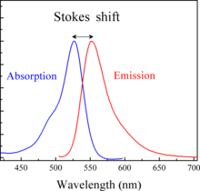
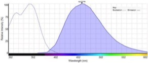 We measure the excitation spectrum, which is often very similar to an absorption spectrum and we measure an emission spectrum. Here that is this curve, which is the fluorescent light emitted by the dye so we characterize these dyes by their excitation maximum, and by their emission maximum. Those numbers tell you immediately a lot about how to use the dye in your actual experiments. The difference between the excitation and emission maximum is called the Stokes Shift, after Sir Stokes who first realized that. There was this difference you can have dyes that have a small Stokes Shift, where the emission is very close to the excitation or you have dyes with a very large Stokes Shift where the emission is very far away from the excitation light.
 Now, so there is energy loss going on, and this causes the difference in wavelength. How does that happen? One of the most useful ways of thinking about that is with the so called Jablonski diagrams. Jablonski was a Polish scientist who did this work in the beginning of the twentith century.
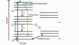 In this Jablonski diagrams, we are looking at the orbitals that electrons can be in when a dye, observes light the electron is going to be kicked to a higher orbital, in a higher energy state, this absorption goes very, very fast. It happens in a time scale of femtoseconds (10^-15 s) and femtoseconds to us don’t mean much! So w like to express this in the distance that light travels during that time period.
This is like those extremely fast. It is pretty amazing that light travels only like 0.3 microns during this time period.
Once that electron finds itself into these higher orbitals, through a process called internal conversion, it quickly falls back to ground level of the excited state. The internal conversion is a tiny little bit of heat that dissipates this way. We have a little bit of energy loss that happens on the level of time scales of picoseconds, i.e. light will travel only 0.3 mm during that time period. Then the electron can hang out there, for what is in comparison to this previous time scales, almost eternity, i.e. something on the order of many nanoseconds. Then it will fall back into the real ground state and emit a photon. That photon will be of energy that is less than the energy that was put in initially. That means that the photon that is coming out, is going to be of a higher wavelength. This return to the ground state is not only the process that can take place when a dye is in an excited state, but also it is possible that the energy is transferred to other molecules. Even the electron can fall back to the ground state but not emit a photon. There is also non-radiative decay. We have a total number of events, some of which result in light coming out, and some of which them that do not. We express the ratio of those two, as the quantum efficiency. The quantum efficiency is a very important parameter of the dye. It not only depends on the dye itself, it also depends on its environment, i.e. for instance what other molecules are around the dye. Nevertheless, quantum efficiency is something you want to know, and that you want to measure, or that you want to be told what it is.
 Another important aspect is the brightness. The brightness in the end is determined by how well the dye absorbs the excitation light and what fraction of the excited state returns to the ground state on the emission of fluorescence. It is determined by both the absorption coefficient and the quantum efficiency.
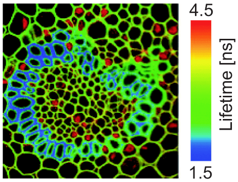
 Now, another important aspect here is what we already talked about, how long does it take between absorbing a dye and for the dye to return to ground state and that is called the lifetime. It is mainly determined by how long it takes before we return to the ground state out of the excited state. Usually this is on the order of nanoseconds. Nevertheless, it is also a parameter that is a dye specific. That is also dependent on the environment of the dyes. There is a whole form of fluorescence microscopy, called Fluorescence LifeTime Microscopy or FLIM that actually reads out Life-Time instead of only reading out fluorescence itself. Nevertheless, what we are now going to discuss is microscopes that discriminates between the excitation light and the emission light. How do we do that in a microscope?
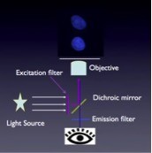
 The main thing is that we use filters. We use filters for exciting light, i.e. we get out of our light source only the light that is of the wavelength that will excite our dye. That light will bounce off of the dichroic mirror, and then excite our sample. After it goes through the objective lens, the sample will start fluorescing. That fluorescence travels back through the same objective and will now pass through the dichroic mirror, then there is an emission filter that will let through fluorescence but that will completely block any scattered excitation light. We only see the fluorescence on our detector, which we have symbolized here with an eye, but that can also be a CCD camera. This is the simple basic principle of a fluorescent microscope.
 The most important aspect here, and the thing that makes it different from a normal microscope is the type of filters. These filters need to be very good, because they really need to discriminate this excitation light from the emitted light. What options do we have there? You can have filters that are based on absorption, i.e. that absorb certain wavelengths of light. Those are not that great in practice, because their spectra are very broad. So, they will also absorb a bit of the emission light. They will not do exactly what we want them to do. The type of filters that we mainly use these days is interference filters. What are those? Interference filters are basically thin alternating layers that have a different refractive index. We get interfaces there that can reflect the light. You can almost think about them as thin transparent layers that are about the wavelength of the light or half the wavelength of the light with semi-reflective coatings in between. What now happens when light hits this filter is that part of it will be reflected. A part of it will move through. The light that reflects will interfere with itself. When the wavelength is such that it matches the wavelength of the light, you will get constructed interference. That constructive interference will then in effect let the light pass through this filter whereas. When the wavelengths are different from the two, the distance between the layers we get destructive interference and it will be reflected out. The filter manufacturers can completely compute how these layers will behave. So they can design in the software what wavelengths this filter should pass through and what wavelengths should be reflected and you can basically order, i.e. any type of filter that you may possible need.
Now, just to make this a little bit clearer there is one example of interference that you are highly aware of, and everyone of us has seen. That is what you see in cell bubbles. In cell bubbles, when light hits that, you will see reflection of all kinds of color of light.
The cell bubble itself has a thickness that is on the order of half the wavelength of a lot of the visible light and you will get the same interference effect where some of the colors will pass through and other colors will be reflected and that gives this beautiful color patterns.
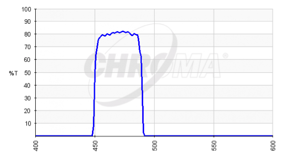
Now we like to explain you how these filters are assembled in a filter cube. We have an example here of such an interference filter, i.e. this one is called HQ470/40, in which 470 is the center wavelength of this filter and the 40 means the bandwidth. This one will pass blue light. If we have a blue LED and hold that up, we see the blue light coming through and you will see that this LED indeed passes it through. With a green light source and hold that up, and go through this filter, you will see that it gets a lot dimmer and not only that, you may also notice that its actually a little bit of blue coming through! Why? That is because the green LED is not purely green, but also has a slight bit of blue light in it.
 The next part is the dichroic mirror. This one is designed such that it reflects blue light. You will not see coming anything through, but if we reflect it toward ourselves, you may be able to see that. The last part is the emission filter that will transmit the green light, and reject the blue light. When we would now place these three in this configuration in the microscope, illuminate from one side go up, we have the objective lens, then the sample, come back through and go through the emission filter. That is the principle of a florescence microscope. This is exactly the way they are arranged in the cubes, where we have an excitation filter, a dichroic mirror, and then an emission filter. So these will, as expected, reflect and you can see it. The exciting blue light will be reflected to the specimen. The specimen will fluoresce green, and that will make it to the eyepiece or to the camera sensor. As discussed in these filter cubes, there’s an excitation filter, there’s a dichroic mirror, and there’s an emission filter.
What’s very important to know and the information you should always have about this filters is their spectra. What are the wavelengths that are being transmitted? And what are the wavelengths that are being reflected? Those spectra then will look something like as follows: we have an excitation filter that passes through the band-pass these wavelengths, these colors of light. The dichroic mirror is made such that it will reflect everything that is lower than a certain cut of band and pass through everything that is higher, and then the emission filter will pass through the higher wavelengths but reject absolutely reject the excitation light. So, when you now assemble
a fluorescent microscope, your task will be to select filters that match well the dyes, that you’ll be working with and what you will be doing in that case is to try to overlay the spectrum of the fluorophores with the spectrum of your filters. We have here a spectrum of a dye that is probably Cy3, the Cyanine dye. It excites in the green areas, around 550nm, and it has en emission maximum around 600nm. If you know use a band-pass filter, that is centered around 650nm, that will easily reject the excitation light, because its far away from that but you also note that the integral of it, that it only passes through a fraction of the emitted fluorescence and that means that you are losing something like 75% or so of the emitted fluorescence. In general you really want to get all the photons that you can, so it is not a perfect situation. If you now switch to a band-pass filter that is slightly lower, that is around, centered around 610nm then you are catching a much larger fraction like 75% or 80% of the emitted photons. You will be much happier because your image will be much brighter.