


Laser engraving of photos and portraits are always fun.
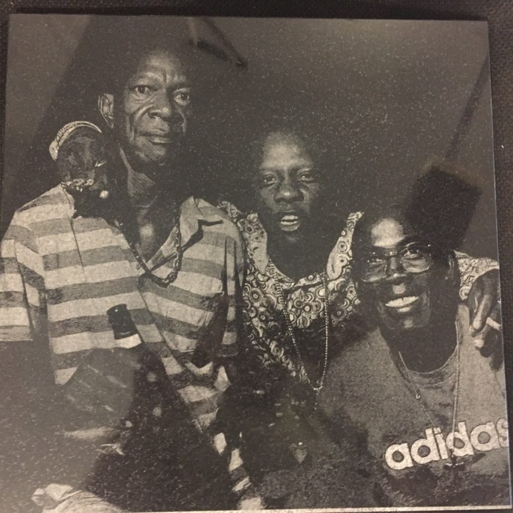
One of the photos we have engraved is shown below:
The process of photo engraving:
Protocol:
Brief:
Photo Engraving of portrait pictures in BMP format on opaque and transparent materials
Laser Power: 13% for cardboard,
Scan Speed: 60mm/s for cardboard
Image Scan Gap (laser dot size): 0.18mm in wood (in high-grained wood this is 0.08mm) and 0.04mm in Acrylic,
Resolution: (25.4mm/in) / (0.18mm/dot)=141 DPI, in the case of cardboard and 600 dpi for Acrylic.
Output Image size: 9” x 6”
Focus Lens: 38.1mm or 1 ½”, Focus Distance: 5.5mm
Introduction: Handling (Tips and Tricks):
The shorter the focal length of the lens, the better resolution of the dots can be generated.
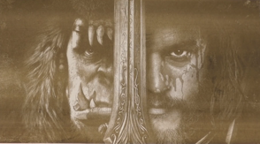
For transparent materials, invert the image.
Sketch is the key element on the image processing.
If the material is more dense in structure (like glass, acrylic, stone), use the lower scan gap size and high dpi (over 330).
If you are using cardboards or thin materials, use small magnets to keep it fully flat during the engraving.
Procedure:
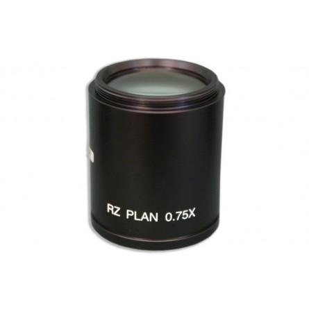
1: Use a laser head lens with the shortest focal length, such as 1 ½” or 38.1mm. The shorter the focal length, the smaller the spot size and shorter depth of focus.
Images below show the result of using 1 ½” focus lens (top) vs. 2” focus lens (bottom), at the same setting of parameters:
2: Determine the best DPI / PPI(dot per inch or pixel per inch)
254 DPI image means 254 dot /in and 1 in=2.54cm or 25.4mm, so it is100 pixel per cm (PPC), i.e. 100pixel/10mm or 1pixel=0.1mm
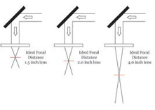
In theory with a 1 ½ “ or 38.1mm focus lens, on a cardboard materials, we can expect to get 0.075mm resolution of a single pixel (hit of a laser light) and with a 2” / 50.8mm focus lens, it will be 0.1mm resolution. In practice, with a 1 ½” or 38.1mm focus lens, we can reach around 0.15mm diameter of one pixel on some cardboard. Pattern to use for estimation of the dot size is shown above.
3: Find the best focal point by scanning the following pattern
Using the 1 ½” or 38.1mm focus lens, start at 6mm distance from the laser head tube and scan it up to 4mm, every 0.5mm, i.e. for 6.0, 5.5mm, 5.0mm, 4.5mm and 4.0mm distances. Then observe the printed pattern images under microscope. Look for separation of dots and thickness of the line. The thinner the line, the better resolution. If dots start joining together, that is not a good choice of focus distance.
As you see above, with 10x magnification, both 6.0 and 5.5mm distance shows better resolution of dots. Between these two, the 6.0mm distance shows some dots start joining up and it is better to go to 5.5mm distance. In addition the 5.5mm distance shows the thinnest line.
4: Next step is using 5.5mm focus distance, and find the actual dot size
We use dots at size of 0.1mm and the gap of 0.1mm, as well as 0.2mm dots to figure out the pixel size (laser hit size) in mm. In other word, we need to figure out what resolution of image we can produce.
The measurement shows the size of dots is 0.18mm on cardboard. This number can be as low as 0.05 on PMME.
5: Calculate the resolution of picture we can produce:
Resolution of a picture is known by PPI or Pixel per inch. We have a 1” or 25.4mm per pixel. How many of the laser dots do we have in one inch:
Lasered output image resolution (dot per inch) = 1 inch / (size of a laser dot) = 25.4mm / 0.18mm = 141 DPI. This is the best resolution of an image we can produce with the lens of 38.1mm at focal distance of 5.5mm, so far.
Note: Changing the output image resolution from 141 dpi to 282 will not cause getting the dots at half size (0.09mm), but it will rather cause to have double dense laser hits. Below image shows 141dpi (left) vs 282 dpi (right):
The conclusion is the white region becomes terribly lost when we use an excessive amount of laser hits by choosing double dpi. If we zoom in the 282 dpi output image, you will see how we loose the resolution (below pic). At below picture black dots are 0.18mm size with 141dpi and red circles represent the 282 dpi. As you see the red circles shows the double burn by overlapping the regions, which results in loosing the white space. Using this dense dpi causes extra amount of laser to hit, and more likely a 3D picture to come out (with depth due to more hits).
6: RDWorks Software:
6.1: Convert the image to grey scale.
6.2: Try to increase the brightness, more than a photography pic is supposed to be, like this (left one is desired):
6.3: We need to resize it to what needs to be lasered to, for instance 6” or 150mm wide.
6.4: The actual image resolution is 600 dpi. Go to Handle > Bitmap handle, drop down the image resolution from 600 to 141 dpi. Thus we set the output image resolution to this number, apply the source then OK.
Result of the full image (left) and dotted picture after zoom in
7: Set the Laser Parameters:
Calculate the proper speed, which results in around 60 mm/s
Scan Mode
No Below Air
Power: start at 12 or 13% which needs to be optimized from 9% to 15%
Interval: 0.18mm
7.1: Calculate the speed:
The amount of time that takes for a single laser bit to move is 3ms. You may try 4ms or 5ms numbers as well.
Speed (in mm/sec)= travel distance / time = 0.18mm / 3ms x (1000ms/1s)=60mm/s
Experience of the printing speed vs DPI: https://www.youtube.com/watch?v=bSsaYZTmAGo
| Image | Print speed | Laser speed |
| 150 dpi | 24 in/s or 610mm/s | 60 mm/s |
| 203 dpi | 14 in/s or 356mm/s | 36mm/s ?? |
| 300 dpi | 12 in/s or 305mm/s | 30mm/s ?? |
| 600 dpi | 6 in /s or 152mm/s | 15 mm/s ?? |
8: Optimize the proper laser power, around %9-15%
You can run multiple tests of the following pattern at 9% till 15% with 1% increase to find the lowest possible power, which burns. Look at the relative darkness of the lines and dots, to see what lower power can generate that matching quality of lines and dots.
In comparison, the 13% power gives better resolution of dots than 12% and thinner line than 14%. Meanwhile the dots start making joining up at 14%
9: Use the bottom left corner, to start up.
10: Make sure you keep the lid is closed and have uniform airflow for exhaust.
11: Final Image which may take an hour to get:
Notes: you won’t see any 3d, it might be little in the black region under chin. The image has great details of hairs and its brightness, but little bit not bright eyes. However, the iris inside eyes can be seen well.
References:
1. RDWorks Learning Lab 115 The Russ Formula for Photo Engraving
Reviews
There are no reviews yet.